A color image can show that an object is present, yet it cannot tell the robot whether that object is 40 centimetres or four metres away. A depth map adds this missing distance information while keeping the familiar image grid.
1. What is a Depth Map?
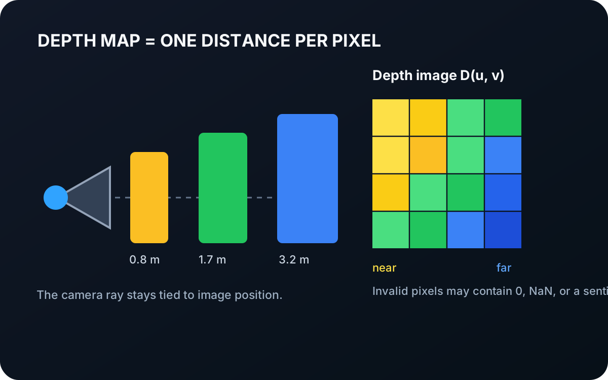
A depth map is a two-dimensional array in which each valid pixel stores the estimated distance from the camera to the visible surface at that image position. It is also called a depth image because its rows and columns align with image pixels.
For an image position , write the depth as
is the depth map, is the pixel position, and is the measured or estimated depth. Depending on the camera and API, may mean distance along the camera’s forward axis or range along the viewing ray. Engineers must check this convention before using the values geometrically.
1.1 A Depth Map Is Not a Photograph
Nearby and distant surfaces are often displayed with different colors, but those colors are only a visualization. The stored value is normally a scalar distance, such as metres or millimetres.
Depth may come from several sources:
- A stereo system compares corresponding locations in left and right camera images.
- A time-of-flight sensor measures how long emitted light takes to return.
- Structured light measures the deformation of a projected pattern.
- A monocular model predicts depth from one image using learned visual cues.
These sources have different guarantees. Calibrated stereo or active depth can recover metric distance. A monocular model may produce only relative depth unless it was designed and calibrated for metric prediction.
1.2 Missing and Uncertain Depth
Not every pixel has a trustworthy value. Reflective, transparent, textureless, very dark, or occluded surfaces can produce invalid depth. Implementations may encode invalid values as zero, NaN, infinity, or a special maximum value.
Depth noise also grows under difficult geometry. At an object boundary, one color pixel may observe the foreground while the depth estimate mixes foreground and background. A visually smooth depth map can therefore hide errors that matter for grasping.
1.3 From a Depth Pixel to a 3D Point
With a calibrated pinhole camera, a depth pixel can be back-projected into camera coordinates:
, , and are the point coordinates in the camera frame; and are pixel coordinates; and are the principal-point coordinates; and and are the camera focal lengths expressed in pixels.
Repeating this calculation for every valid pixel converts the depth map into an organized point cloud. A calibrated rigid transform is then needed to express those points in the robot base frame.
Interactive back-projection
Turn one depth pixel into a 3D point
The camera intrinsics map image position to a viewing ray. Depth chooses where the 3D point lies along that ray.
2. What a Depth Map Tells the Robot
| Depth provides | Depth does not provide by itself |
|---|---|
| Distance to visible surfaces | Object identity |
| Relative foreground/background ordering | The hidden back side of an object |
| Data aligned with image pixels | A robot-frame coordinate without calibration |
| A route to 3D points | Guaranteed accuracy on reflective or transparent materials |
The useful mental model is: a color image records appearance, while a depth map records visible surface distance on the same kind of grid. Combining them lets the robot ask both “what is this pixel?” and “how far away is it?”
2.1 The Telekinesis DepthImage Datatype
Telekinesis represents metric depth with datatypes.DepthImage. Its depth array has shape (H, W), uses a floating-point datatype, and stores distances in metres. It can also carry an optional aligned RGB image with shape (H, W, 3).
import numpy as np
from telekinesis import datatypes

depth = np.ones((480, 640), dtype=np.float32)  # metres
depth_image = datatypes.DepthImage(depth)
The unit is part of the contract. A value of 1.2 means 1.2 metres—not 1.2 millimetres or an arbitrary display intensity.
3. Where to Go Next
 Basic · 3 min read
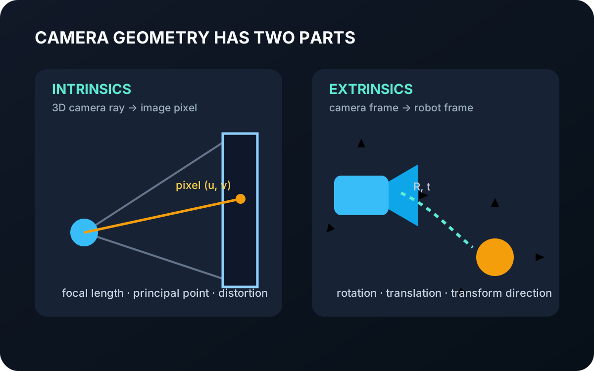
What are Camera Intrinsics and Extrinsics?
Camera intrinsics describe how 3D rays map to pixels, while extrinsics place the camera in another coordinate frame. Learn why robots need both and how Telekinesis represents them.
Read tutorial →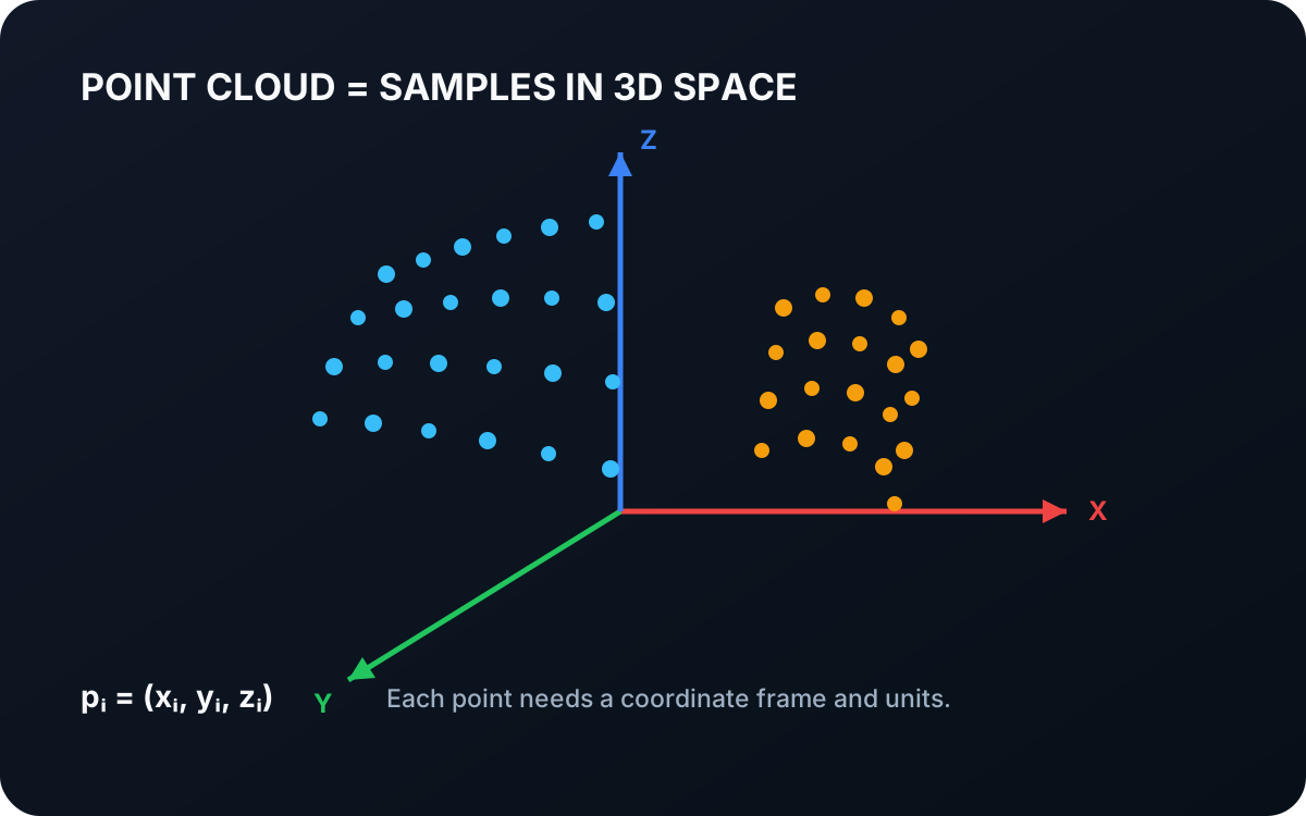 Basic · 4 min read
What is a Point Cloud?
A point cloud is a collection of sampled positions in three-dimensional space. Learn how points represent visible geometry, why coordinate frames matter, and how depth images become spatial data for robots.
Read tutorial →