Imagine an AMR navigating a warehouse. Its camera produces a wide 1920×1080 image, while its object detector accepts a square 640×640 image. Stretching the camera image into that square makes round wheels look oval and changes the proportions the detector sees. Preserving the proportions requires empty padding, which shifts the detector’s coordinates. Geometric image transforms prepare the image while keeping enough information to map every result back to the AMR’s camera.
1. What are Geometric Image Transforms?
Geometric image transforms create a new pixel grid by mapping coordinates back to an existing image. This tutorial explains resizing, aspect fitting, rotation, translation, cropping, padding, interpolation, and coordinate recovery through Pupil.
The scene itself does not move when software resizes an image. Its numerical representation moves to a different coordinate system. Any box, mask, contour, keypoint, or camera model associated with the original grid must be transformed consistently.
1.1 The Geometric Transform Pipeline
Source coordinates → resampled output grid
A transformed image is only useful for robotics when boxes, masks, keypoints, and camera coordinates follow the same mapping.
Imagine preparing the AMR’s wide camera image for its square model input. The first decision is the shape of the new output image: should the source be stretched to fill it, scaled without distortion and padded, or cropped? That choice determines the relationship between the camera coordinates and model coordinates.
Once the output grid is known, the transform visits each output pixel and asks where that location came from in the source image. The answer is often between source pixels rather than exactly on one. An interpolation rule must then estimate the value from nearby samples. If the mapped location falls outside the source image, a padding rule supplies the missing value.
The result looks like a new image, but it is also a new coordinate system. A box at in the transformed image does not refer to the same camera ray as in the original camera image. Scale, padding, crop offset, and rotation must therefore travel with the image so detections can be mapped back correctly.
The interactive diagram lets you compare these choices before we describe their mathematics. Watch what happens to the circle: stretching changes its shape, aspect fitting preserves it but adds padding, and rotation may require a larger canvas to avoid throwing pixels away.
Interactive mechanism
Change the image grid without changing the scene
1.2 Forward and Inverse Mapping
Suppose an industrial arm rotates an image so a part appears upright before inspection. The software must know where every point on the original part should appear after that rotation. A geometric transform is the rule connecting each source coordinate to its output coordinate.
A forward mapping answers, “where should this source point move?” Translation adds an offset, scaling multiplies coordinates, and rotation mixes the horizontal and vertical axes. An affine transformation collects those effects in one matrix:
is a source coordinate, is its output coordinate, describe scaling, rotation, or shear, and are translations.
Forward mapping sends each source sample to an output position. Because transformed coordinates are rarely integers, several source pixels may land near one output pixel while others receive none. Production resampling usually uses inverse mapping: visit each output pixel, apply the inverse transformation, and sample the source at that location. Every output location then receives a defined value.
1.3 Interpolation Decides What a Fractional Pixel Means
When a humanoid enlarges an image crop around a small medicine bottle, inverse mapping may say that an output pixel came from source position . No camera pixel exists at that fractional coordinate. Interpolation decides what value should represent it, and the right rule depends on whether the data is a photograph, a depth image, or a class mask.
Nearest-neighbor interpolation selects the closest source pixel. It is fast and preserves discrete mask labels, but produces blocky edges when enlarging.
Bilinear interpolation combines the four surrounding samples. If the fractional source position has offsets and within a cell, then
are the four neighboring intensities. Bilinear interpolation is smooth and efficient, but it invents intermediate values. That is appropriate for photographs and dangerous for category-ID masks, where an average of labels 1 and 2 is not a class.
Bicubic interpolation uses a wider neighborhood and can look sharper when enlarging, at greater cost and with possible ringing. Area-style interpolation is often useful when shrinking because it integrates source coverage rather than dropping samples.
1.4 Downsampling Requires Anti-Aliasing
Imagine shrinking an aerospace image containing tightly spaced carbon-fiber texture or fine ventilation slots. The smaller image grid cannot represent every alternating light and dark line. If those details are sampled directly, they can reappear as false stripes or waves instead of simply disappearing.
When an image shrinks, multiple source pixels must become one output pixel. Fine alternating patterns may exceed the new grid’s sampling capacity and appear as false lower-frequency patterns called aliasing.
A sound downsampling pipeline low-pass filters before subsampling. Gaussian pyramids make this explicit: smooth, then reduce the width and height, usually by two. Each level represents a coarser spatial scale and supports efficient multi-scale search.
Upsampling cannot restore frequencies removed during downsampling. It creates more samples through interpolation, not more captured detail.
1.5 Aspect Ratio, Letterboxing, and Coordinate Recovery
Return to the warehouse AMR. Its detector requires a square input, but pallets, people, and aisles were captured in a wide image. Stretching width and height independently changes their apparent shape. Aspect fitting uses one shared scale for both axes, then fills the unused area with padding. This preserves proportions at the cost of introducing a coordinate offset.
For a source of width and height fitted into target dimensions , the shared scale is
The resized dimensions are and . Centered padding offsets are
A source point maps to , . To bring a model prediction back, use and . , , and must travel with the transformed image.
Failing to remove letterbox padding is a common robotics error: boxes look plausible on the model input but shift when projected onto the camera or depth image.
1.6 Rotation Changes Both Pixels and Canvas
An aerospace industrial arm may rotate a wing-panel image so rows of fasteners run horizontally before measurement. Turning the image seems simple, but its rectangular boundaries do not rotate with the part. Corners may fall outside the original limits, while empty regions appear elsewhere. The pipeline must choose a center and decide whether to crop evidence or enlarge the output image.
Rotation about a center uses
is the rotation angle. Keeping the original canvas crops corners; expanding the canvas preserves content but adds a translation and changes dimensions. Border handling determines values in newly exposed areas.
Rotation is not a substitute for camera calibration. Rotating an image upright may help a model, but rays associated with pixels have changed and must be mapped back before metric projection.
1.7 Cropping and Padding Define a New Origin
A logistics AMR may detect a shipping label, crop that region, enlarge it, and run OCR. Cropping does not distort the label, but the top-left corner of the crop becomes a new coordinate origin. If OCR later identifies a damaged area that must be located in the full camera image, the crop offset is essential.
Cropping a rectangle beginning at maps a crop coordinate to source coordinate . Polygon cropping additionally masks pixels outside the selected shape. Padding moves the old origin by the left and top pad amounts.
These operations are useful after detection: crop the requested object, resize it consistently, then run inspection. Preserve crop metadata if results must return to the full camera image.
1.8 Follow One Detection Through Letterboxing
The formulas become easier to trust when we follow a real coordinate through them. This example shows why remembering the scale alone is insufficient and why a forgotten pad can move a robot target by hundreds of pixels.
Consider a 1920×1080 camera image fitted into a 640×640 model input. The common scale is , so the resized image is 640×360. Centering it adds 140 pixels above and 140 below. There is no horizontal padding.
Suppose the detector returns the model-space center . That point is not mapped back by multiplying both coordinates by three. Padding must be removed first:
Here, is the center of the original camera image. Ignoring the vertical pad would produce , a plausible image coordinate that points far below the true object. This is why coordinate bugs can survive casual visual inspection.
Boxes use the same rule on both corners. Masks require a full inverse warp: remove the padded bands, resize to the source dimensions with nearest-neighbor interpolation for categorical labels, and place the result in the original camera image. Keypoints, contours, and polygons require the inverse coordinate mapping. Treat the transform parameters as part of the inference result, not temporary preprocessing variables.
1.9 Images and Camera Calibration Must Stay Consistent
So far we have treated coordinates as locations in an image. A robot eventually uses them as viewing rays in 3D, which adds a stricter requirement: the camera calibration must describe the same pixel grid as the measurement.
A calibrated camera associates every pixel with a viewing ray through an intrinsic matrix. Cropping changes the principal-point coordinates. Resizing changes focal lengths and the principal point by the scale. Padding shifts the principal point. If a transformed image is used directly with the original intrinsic matrix, reconstructed 3D rays will be wrong even if the 2D overlay looks reasonable.
There are two safe patterns. Either map detections back to the untouched camera image before using depth and calibration, or update the camera intrinsics for the exact crop, scale, and pad. The first pattern is often easier to audit because all metric reasoning occurs in one stable coordinate system.
This also explains why arbitrary image rotation is more than a display choice. Rotation changes pixel axes, and an expanded canvas adds an offset. If a robot uses the rotated coordinates with unrotated depth or calibration, it mixes two geometries.
1.10 A Practical Choice Table
Each operation solves a different preparation problem and creates different metadata that must be preserved. Use this table as a final map from the desired outcome to the transform and bookkeeping it requires.
| Requirement | Operation | Important record |
|---|---|---|
| Faster processing | Downsample | Scale and anti-aliasing method |
| Fixed model size without distortion | Aspect fit | Scale and padding offsets |
| Isolate a detected object | Bounding-box crop | Crop origin and original dimensions |
| Align a known orientation | Rotate | Center, angle, expanded-canvas offset |
| Add safe context | Pad | Top and left offset plus border rule |
| Multi-scale processing | Gaussian pyramid | Level and cumulative scale |
2. How to Prepare an Image With Pupil
The most common deployment task is fitting a camera image into a model’s fixed input without changing object proportions. The example therefore uses aspect fitting and makes the target canvas, padding color, and interpolation method explicit.
from telekinesis import datatypes, pupil

image = datatypes.Image.from_url(
    url="https://assets.telekinesis.ai/examples/v1/images/gearbox.webp"
)

model_input = pupil.resize_image_with_aspect_fit(
    image=image,
    resize_width=640,
    resize_height=640,
    pad_color=(128, 128, 128),
    interpolation_method="linear",
)

print(model_input.shape)
Choose interpolation by datatype: nearest for categorical masks, linear for most camera imagery, and an anti-aliased method when reducing resolution. When adding rotation or translation, use their dedicated Pupil Skills and preserve the resulting coordinate mapping alongside the image.
3. How to Validate a Transform
A transform is correct only when both its pixels and its coordinates behave as expected. Transform a synthetic checkerboard with known points, then map those points forward and backward. The round-trip error should remain within the interpolation and rounding tolerance. Test boxes at image corners, masks with single-pixel labels, and odd source dimensions where padding is asymmetric.
For robotics, overlay recovered predictions on the untouched camera image and verify metric projection after mapping them back. A visually correct model input can still produce a physically wrong robot coordinate if scale or padding metadata is lost.
Also verify that image and annotation transforms use compatible interpolation. A photograph may use bilinear resampling while its class mask uses nearest neighbor. Applying the photographic rule to both can create fractional class IDs at boundaries; applying nearest neighbor to both can make the camera image unnecessarily jagged. Shared geometry does not require shared pixel interpolation.
4. Where to Go Next
 Basic · 4 min read
What is an Image?
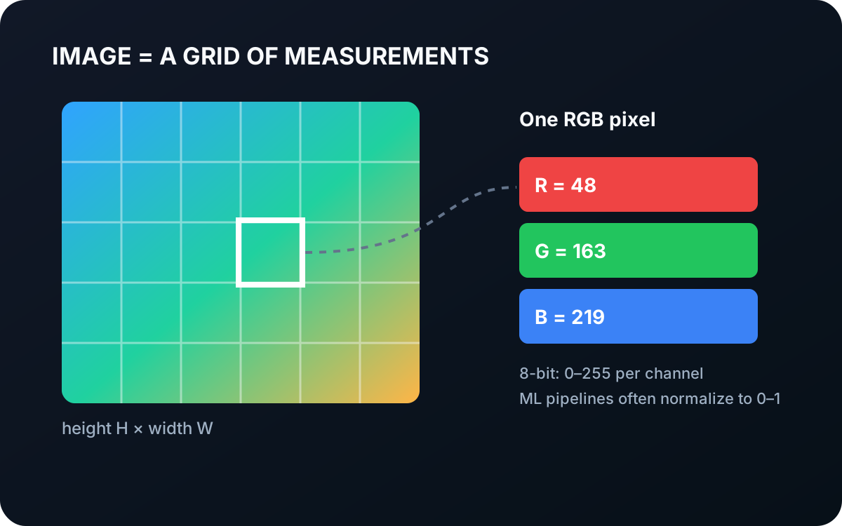
An image is a rectangular grid of measurements captured from a scene. Learn how pixels, channels, resolution, and numeric ranges represent the visual input used by robot perception algorithms.
Read tutorial →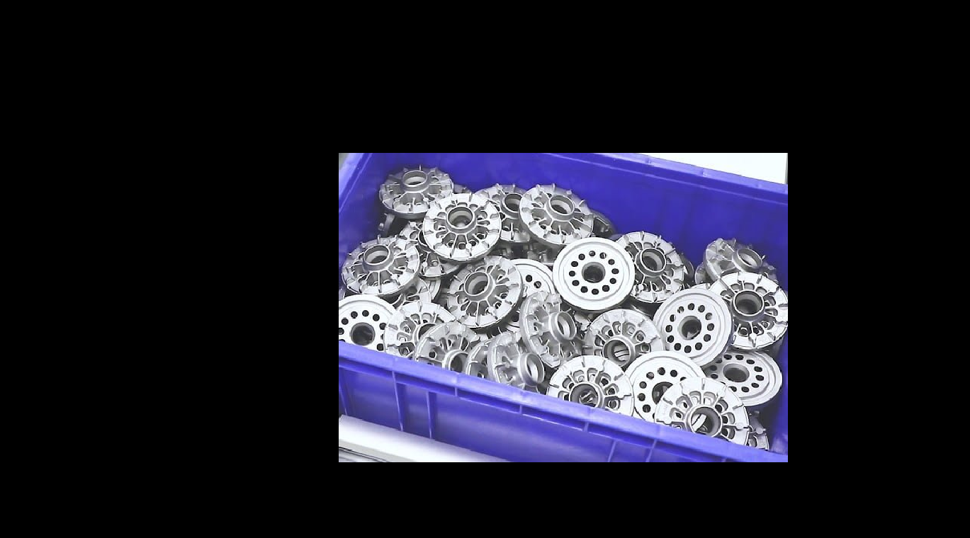 Basic · 12 min read
What is Image and Mask Composition?
Image and mask composition combines aligned pixel grids using logical, arithmetic, channel, or weighted operations. Learn AND, OR, XOR, NOT, difference, split/merge, and overlays, including the datatype and coordinate pitfalls.
Read tutorial →5. References
- Wolberg, G. Digital Image Warping. IEEE Computer Society Press, 1990.
- Telekinesis. “Resize Image With Aspect Fit”, Pupil Skill documentation.
- Telekinesis. “Resize Image”, Pupil Skill documentation.